Timing
HiPERCAM frames each come with a timestamp, but this is taken at a particular part of the exposure cycle, and not at the mid exposure point. There is therefore a requirement to offset from this timestamp to deduce the mid-exposure time. The purpose of this document is to detail how this is achieved for each readout mode. It is technical in nature and unlikely to be of interest for most observers.
No clear mode
This is the standard mode for observing with data accumulating during the readout of the previous frame. Fig. 6 illustrates the readout sequence in no clear mode.
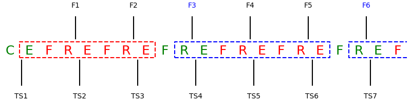
Fig. 6 The no-clear mode read sequence. ‘C’ stands for ‘clear’, ‘E’ for the exposure delay, ‘F’ for a frame transfer, ‘R’ for the readout. The dashed boxes show the section during which photons accumulate. The labels at the top show when the respective frames are read, while those along the bottom indicate when timestamps are taken. The timestamps in this case are takn just after the frames are read so that frame 3 carries time stamp 3. The figure assumes that NSKIP=2 applies to the CCD, i.e. 2 out of 3 of the reads actually read junk data because the immediately preceding ‘F’ is a dummy (marked as such by being in red). The first dashed box is marked in red as it is a special case since there is no previous frame readout; all subsequent frames are the same and marked in blue.
In the case shown, NSKIP=2, so that useful data appears every third frame. Thus F3 and F6 are proper data and appear after a real frame transfer and read, whereas the 5th frame (F5) is junk data following a read of the masked off area when there was no frame transfer. F6, which is the first of the ‘regular’ exposures, unaffected by end-effects at the start. The exposure upon which it is based is marked by the blue box. It starts immediately after the (genuine) frame transfer that occurs after the third time stamp (TS3) is taken. The data moved into the masked area from this frame transfer appear as F3, but photons accumulate in the imaging area up to the frame transfer that occurs after TS6. Thus the fundamental cycle period is 3 = NSKIP + 1.
The mid-exposure time we want in the average of the start and end times. We
reference these with respect to TS6, since that is the time stamp that will be
tacked on to F6 and is the “per-frame” timing data referred to earlier.
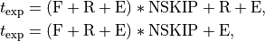
Adopting an obvious notation, the time of the end of the exposure,
 , is given by

while the start time is

The average of these is the mid-exposure time that we want, i.e.
(1)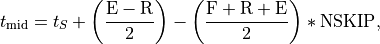
Here  is the timestamp of the frame in question, while F,
R and E are the times taken to frame transfer, readout, and
the exposure delay (user defined). Eq. (1) applies to frame
number
is the timestamp of the frame in question, while F,
R and E are the times taken to frame transfer, readout, and
the exposure delay (user defined). Eq. (1) applies to frame
number 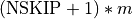 , where
  is an integer,
 . e.g. in the example,
  ,
,
 gives the time for F6. Times are meaningless for any of the
dummy frames (F2, F5 etc) since they don’t contain data, which leaves the
gives the time for F6. Times are meaningless for any of the
dummy frames (F2, F5 etc) since they don’t contain data, which leaves the
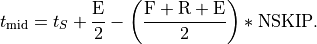
 case, F3. The exposure for this is high-lighted in red in
Fig. 6. If it is compared to the blue box, it can be seen to lack
the ‘R’ stage at the start relative to that, so we can take
Eq. (1) and add
case, F3. The exposure for this is high-lighted in red in
Fig. 6. If it is compared to the blue box, it can be seen to lack
the ‘R’ stage at the start relative to that, so we can take
Eq. (1) and add  to get the special case for the first
(non-junk) frame:
to get the special case for the first
(non-junk) frame:
The exposure times are given by
for the normal ( ) and special () cases respectively,
while the dead time between exposures is
) and special () cases respectively,
while the dead time between exposures is

In the code, hipercam.hcam, these are implemented by computing
two offsets plus two multipliers for NSKIP with names like toff1 etc,
representing the constant offset and the pre-factor that multiplies NSKIP
(called tdelta in hipercam.hcam).
Clear mode
Although clear mode is less useful than clear mode for timing work, I go through the same analysis here.
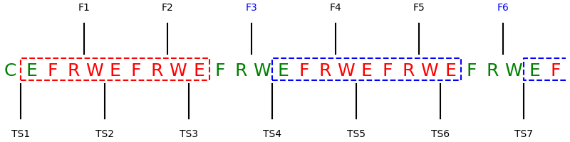
Fig. 7 The clear mode read sequence. The keys are the same as before but with the addition of ‘W’ for wipe.
Fig. 7 shows the clear mode case. The difference is that after each readout there is now a genuine wipe, although with nskip in operation, some of these are simply short delays to keep synchronisation. That means photons that accumulated in the imaging area during readout of the masked area are thrown away, and the exposure only starts once the wipe is completed. This allows shorter exposures which can be useful on bright objects, although at the cost of increased deadtime. It is however often useful for calibrations, e.g. bright flux standards. The start and end times in this case are
One finds the mid-exposure, exposure and dead times to be
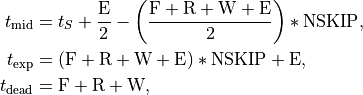
there being no distinction in this case between the first fram and all the others.
Drift mode
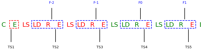
Fig. 8 The drift mode read sequence. The key is the same as before but with the addition of ‘LS’ and ‘LD’ for line-shift and line-dump. In this case ‘DRIFT NWINS’ is taken to be 3 in which case the first real data frame, F1, gets TS4 attached to it.
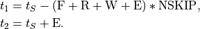
In drift mode the windows are partially shifted into the masked area so that there are one or more of them in the masked area as windows are being read out. The smaller shifts allow the deadtime between exposures to be reduced but create an offset between the timestamps and data. Ignoring the drift window offset initially, the start and end times are given by
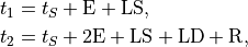
where R is given by the header parameter ‘ESO DET READ’, LD by ‘ESO DRIFT TLINEDUMP’ and E by ‘ESO DET TDELAY’ (see Summary of symbols and corresponding header parameters for a complete listing). Accounting for the drift window offser, the times of interest work out to be
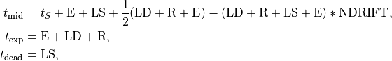
where NDRIFT is the number of drift windows, ‘DET DRIFT NWINS’ in the headers.
All the relations above are implemented within hipercam.hcam. Results
from tests with a precisely synchronised LED can be found in
Timing tests.
Note
There is no NSUB option in drift mode, therefore tdelta in
hipercam.hcam is set = 0.
Summary of symbols and corresponding header parameters
Here is a summary table of all the symbols used above with the corresponding mode and equivalent FITS header parameter:
Symbol |
Mode |
FITS header parameter |
|---|---|---|
E |
ALL |
ESO DET TDELAY |
R+F |
CLEAR |
ESO DET READ |
R+F |
NO CLEAR |
ESO DET READ |
R |
DRIFT |
ESO DET READ |
W |
CLEAR |
ESO DET TCLEAR |
F |
NO CLEAR |
ESO DET TFT |
LD |
DRIFT |
ESO DRIFT TLINEDUMP |
LS |
DRIFT |
ESO DRIFT TLINESHIFT |
NDRIFT |
DRIFT |
DET DRIFT NWINS |
Note
The header parameter ‘ESO DET READ’ corresponds to the sum of the readout R and frame transfer F that occur in the clear and no-clear modes (there is no frame transfer in drift mode).