HiPERCAM’s windows format
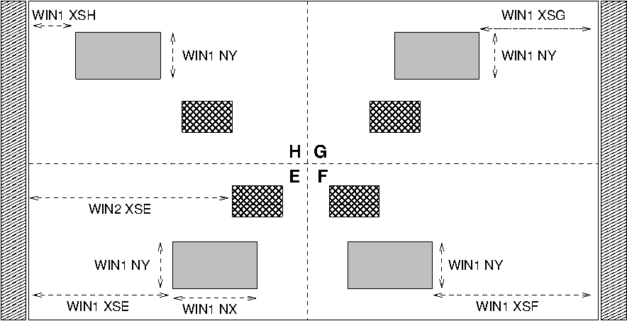
Fig. 5 Figure showing how the HiPERCAM windows are defined. The thin rectangles at the left and right of the imaging area represent the “pre-scan” (zero light) regions.
Although it is not usually necessary to know the details of HiPERCAM’s window structure, it may help in somce cases. Fig. 5 illustrates the main points, which are:
Each CCD is split into 4 quadrants labelled E, F, G, H. These have dimensions 1024 in X by 512 in Y, making the whole imaging area of each CCD 2048 by 1024 pixels.
The outputs are located at the corners of the CCD (somewhat more in fact if one allows for an equivalent masked area). Parallel transfers are in the Y direction towards the respective output, while the serial register moves charges in the X direction towards the respective output.
In windowed mode there can be either one or two windows per quadrant. The sizes of these windows are the same in all quadrants in sets of four. i.e. If you have one window per quadrant of dimension WIN1 NX by WIN1 NY in quadrant E, it will have the same dimensions in quadrants F, G and H, but you can have another window, dimensions WIN2 NX by WIN2 NY, that can be different from the first, but again will be repreated in all quadrants. The two windows must not overlap in the Y direction.
The location of a given set of windows is defined by parameter YS as in WIN1 YS indicating the Y-position of the first row to be read out relative to the quadrant’s output. If it was actually the very first row of the quadrant that could be read, the YS would be set = 1. The value of YS is the same for all four windows of a given set. The X-locations of the windows are independently set by four parameters, one per quadrant, giving the position of the first column to be read out relative to the quadrant’s output. These are called XSE, XSF, XSG and XSH with a WIN1 or WIN2 qualifier. e.g. WIN1 XSE says where the left-most pixels of the first window in quadrant E fall in terms of columns. This would = 1 if it lined up with the extreme left of the CCD.
The windows can be be binned in both X and Y.
There can be pre-scan pixels (see Fig. 5) in the data. The pre-scans are 50 pixels (unbinned). If used, then the X-binning must divide into 50.